Work in Progress: Voyager Desktop Computer
Following my recent “show-off” post presenting my Voyager Desktop Computer, let’s now have a detailed look at how I built this prop, going through every step, from the raw parts all the way to the finished unit, covering the concepts of different aspects of the prop, the construction of several custom parts, the installation of the electronics and the assembly of everything to bring it all together. Although I didn’t snap an image of every step along the way, it’s more than a hundred progress pictures, so I hope you brought a little time…
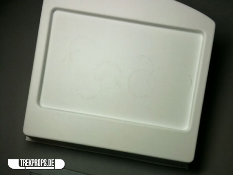
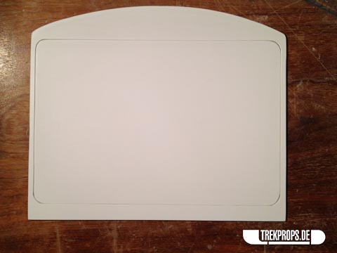
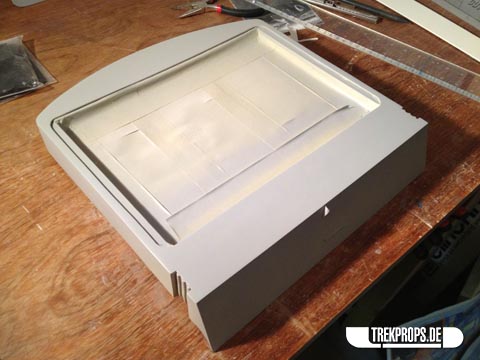
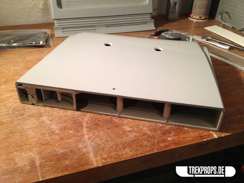
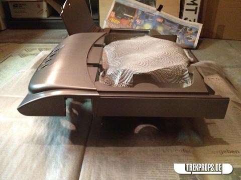
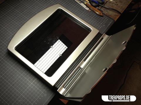
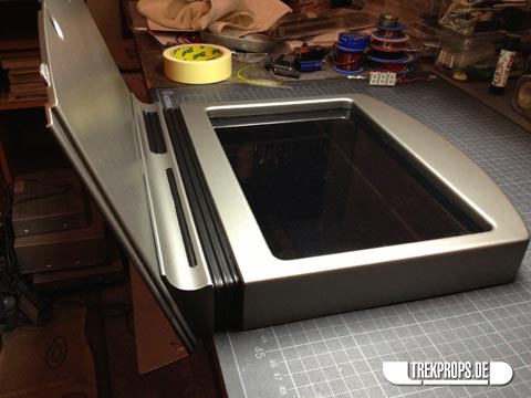
It all started with a kit that I got from a fellow collector, which contained three items: The screen, made from vacuformed styrene plastic (pictured in the following image), the connecting piece between the screen and the base, cast in solid resin and the black acrylic detailing pieces for the “keyboard/trackpad” and such.
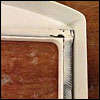
Starting with the screen, the first task was to trim the excess plastic to make sure the display had the correct depth as well as cutting out the middle part where the actual screen would go. Since the plastic used to vacuform this part was quite sturdy, this was no easy thing to do. A sharp X-acto knife and a bit of patience did the trick however.
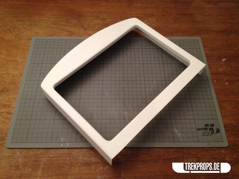
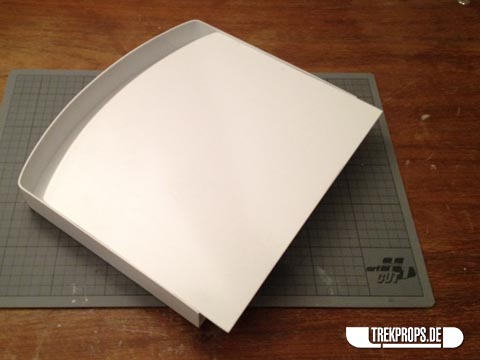
Next I had to make a cover for the back of the display that had to fit as perfectly as possible on the vacuformed part. This is where the light source for backlighting the display graphic is going to go.
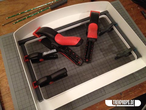
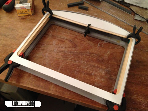
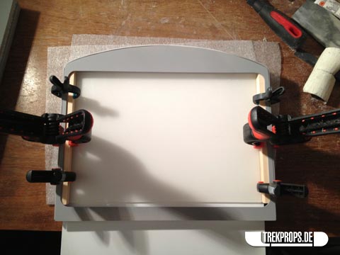
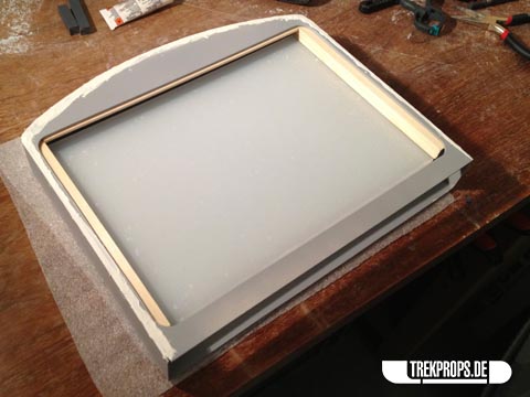
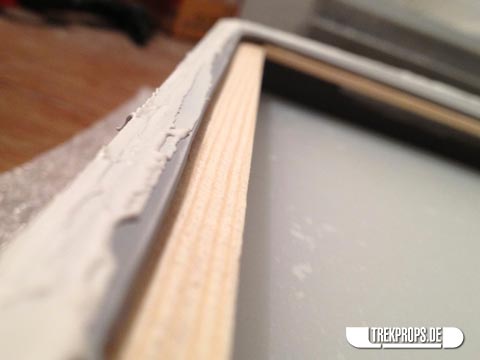
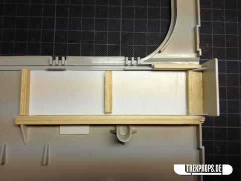
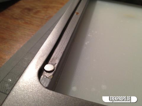
Next I had to figure out a way to attach the actual display to the screen from behind. As mentioned in my “show-off” post, the display consists of a large photographic slide laminated on a piece of smoked acrylic. Because I didn’t want to damage the plexi, I decided not to screw it into the housing, being afraid of cracking it in the process. Instead I decided to glue it in place, which meant that I needed some kind of frame on the inside to act as a surface for the glue to stick to. To that end I glued in four solid beams along the edges of the screen and filled the remaining gaps with putty. By the way, glueing in the display was not the best idea. Even though I used a very strong two-component epoxy glue, it didn’t stick firmly in place and partly came off later. Luckily I was able to repair it and bond it (hopefully) permanently, but in hindsight I should have tried to carefully screw it on for a foolproof fixture. Oh well, live and learn, right?
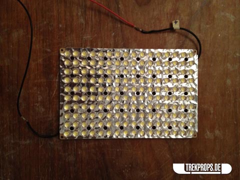
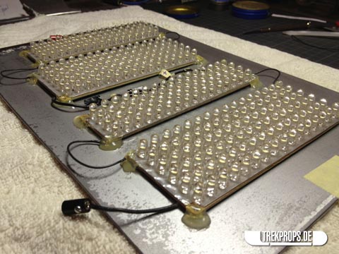
Going forward I then looked after the backlight and tested different ways to position the LEDs behind the screen. I also experimented with different light diffusion options. Needing a lot of light, I decided to use two LED video lights – namely those which normally are used while filming with a DSLR. They don’t need a lot of power and are very bright yet inexpensive, which was exactly what I needed. Each one of the lights I used have 160 ultra-bright white LEDs, which gave me a whopping 320 LEDs to work with. Here’s one of those lights stripped of its casing:
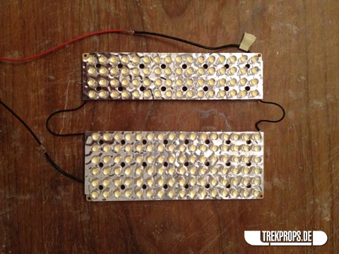
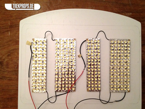
Trying to spread the light as evenly as possible inside the screen, it quickly became clear that I had to physically detach the LEDs from each other and scatter them over the available area on the back of the screen a bit. So I cut each of the circuit boards in two parts to be able to put some space between them:
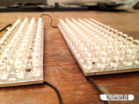
Here you can see some early lighting tests. Looks pretty good already!
The neat thing about the combination of real photographic film and a smoked plexi in front of it is that the screen appears almost completely black when the backlight is turned off. The reflective qualities of the acrylic make it look very shiny which I especially like. 🙂

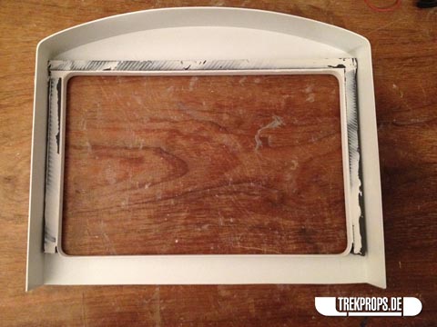
Having the lighting all figured out, I was ready to install the display and move on with the screen as a whole. I wanted all of the inner workings of the prop to be completely serviceable and that of course included the electronics inside the screen. To make that happen I had to cut a panel out of the rear cover like so:
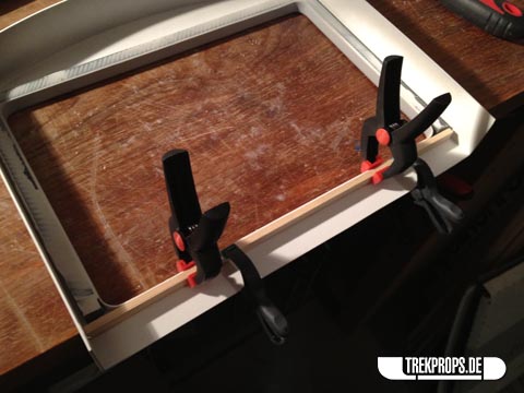
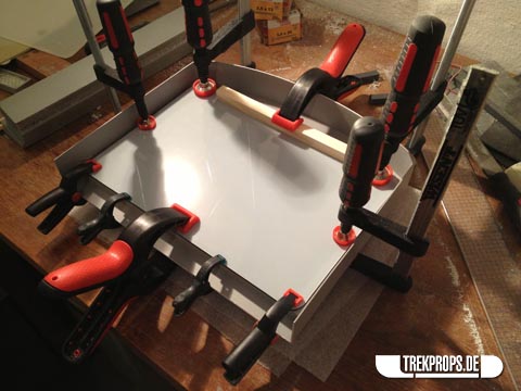
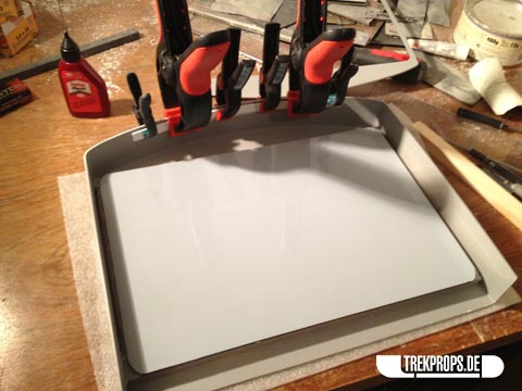
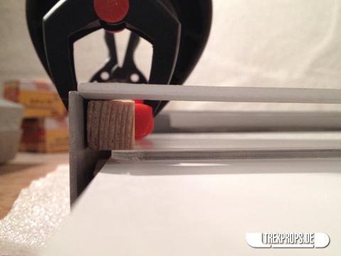
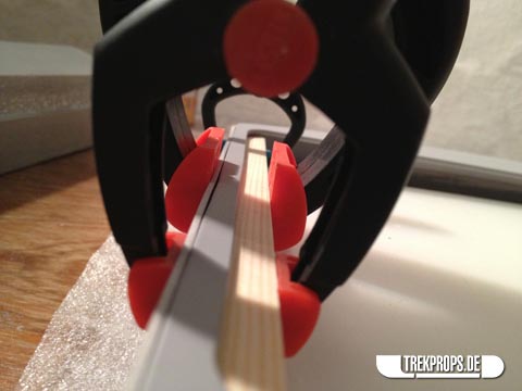
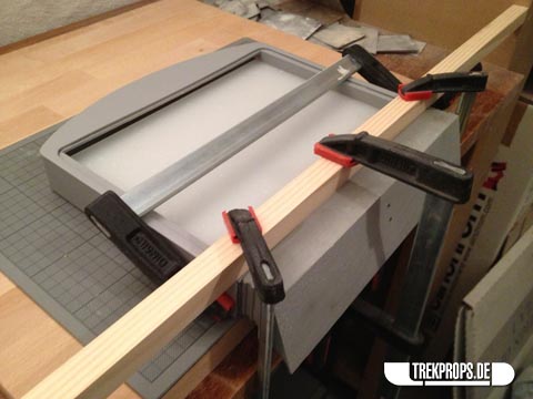
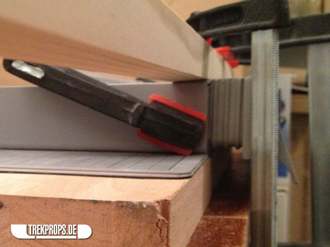
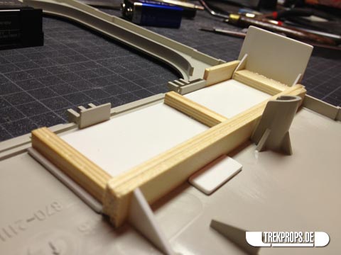
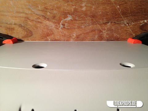
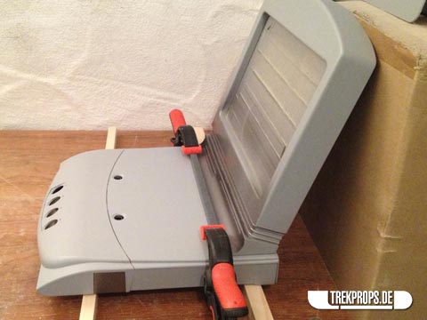
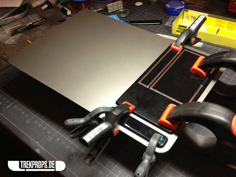
And here’s the frame clamped in place together with three wooden strips for support. These strips will later also hold the magnets which keep the back cover in place. Additionally they will secure the main diffusion panel, which will be glued to the underside of them.
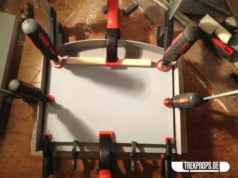
Next I glued the display screen onto its frame.
The white film you can see behind the plexi here is the first layer of diffusion by the way: A translucent film laminated to the back of the display slide, which is in turn laminated to the back of the smoked plexi.
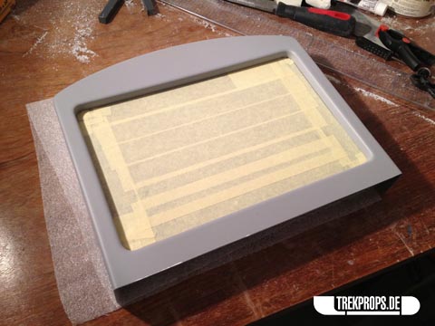
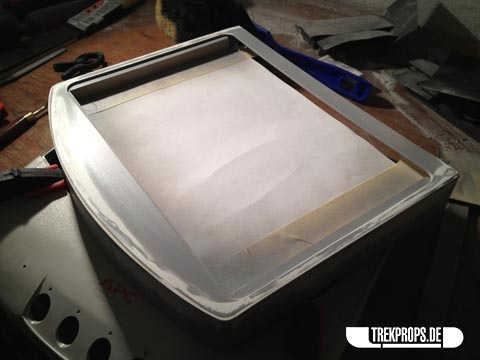
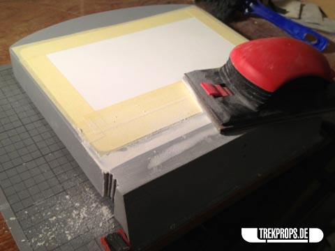
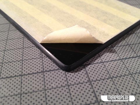
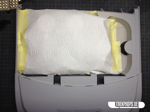
To protect it from primer and paint, I covered the front facing side using masking tape:
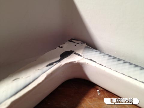
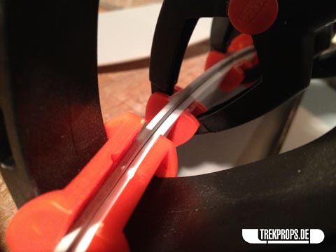
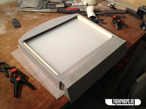
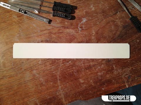
With the screen panel in place, the next step was to install the additional layers of diffusion and to attach the back frame to the rear of the chassis. First however I had to create a lip on the upper inside of the screen as support for the back frame. I used a strip of styrene for that. Without it, there would’ve been no way to attach it properly.
Next up was the main diffusion panel which is composed of a clear piece of acrylic, laminated from both sides with more translucent adhesive foil to spread the light even further on its way from the LEDs to the display. To attach it inside the screen, I used two of the wooden strips mentioned above, which I glued to the sides inside the casing. I glued the diffusion panel onto those strips first, however, and upside down. Then I rotated both and glued all of it inside the screen. Sounds complicated, I know, but hopefully the following pictures will make my process clear.
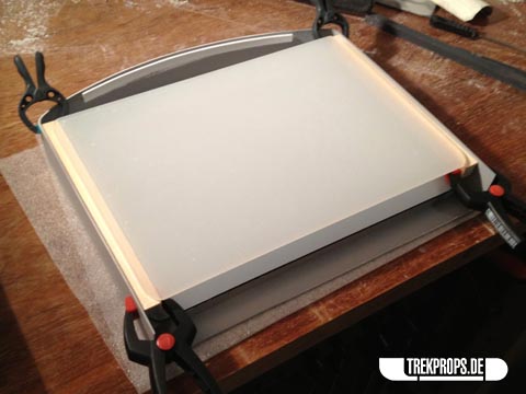
Diffusion panel rotated and back frame placed on top:
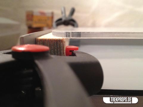
Here you can clearly see one of the support strips for the back cover, which will later house some of the magnets to keep the lid from falling off.
Test fitting the screen and the resin “foot”.
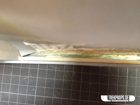
After everything was glued together I filled the outer seams with putty…
… and after a lot of sanding and priming the surface was nice and smooth.
It turned out, however, that the lip I had created inside the screen (for the back frame to rest on) wasn’t enough to ensure a strong bond. So I filled some putty inside the screen after the fact to reinforce the structure.
Then I glued the resin piece connecting the screen with the base inside the screen.
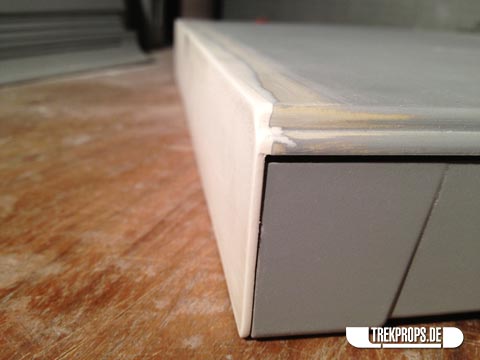
Even though I had carefully measured all the parts and test-fitted them for the best possible fit, the back surface was not as flat as it should have been after the glue had dried. So I had to do quite a lot of sanding to correct the situation.
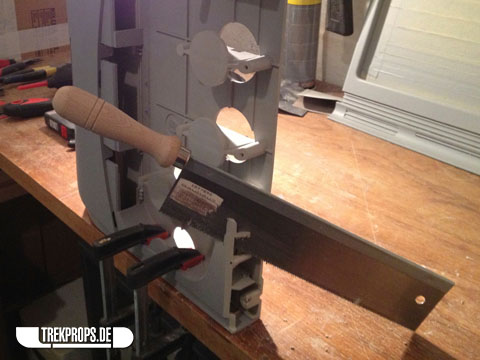
The irregularities were so severe even that sanding by hand just didn’t cut it. I ultimately had to use a belt sander to make it work.
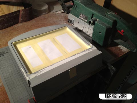
After having some time spent sanding, filling and priming, the surface was perfect. Notice how I masked the inside of the screen so that no dust, debris or primer could get inside. Also notice that all of that didn’t necessarily help… 😉
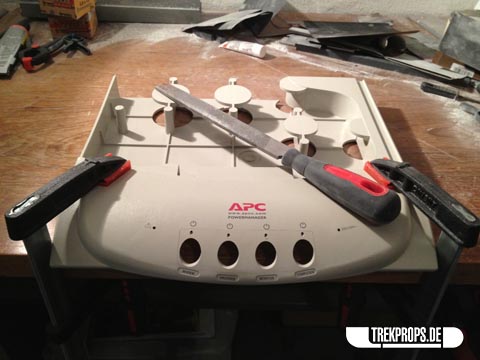
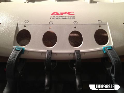
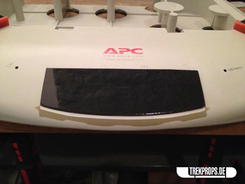
Time to take care of the base unit for a change! The first task was to cut off a good portion of the found item, which is an APC power manager.
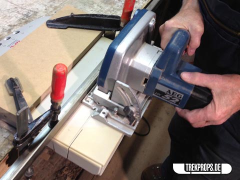
Not having access to some of the fancier equipment like a laser- or water jet cutter, I used a circular saw, which naturally generated quite some heat caused by the friction between the blade and the plastic. The unfortunate result was a very scruffy edge which I painstakingly had to clean up afterwards.
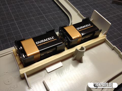
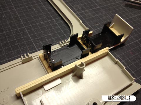
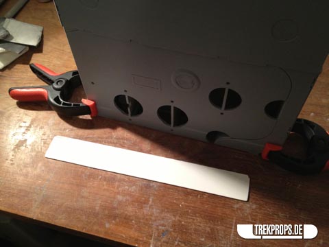
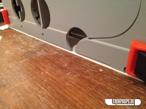
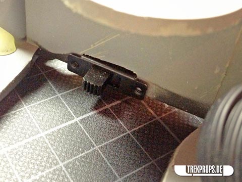
The base unit comes apart and can be disassembled very easily. So I was able to comfortably work on the battery holder without any problems. I decided to hide it inside one of the former power plugs on the right side and devised a sliding mechanism to be able to replace the batteries effortlessly. The holder is made of styrene plastic and a few wooden strips, glued together in such a way that it can accommodate two 9V block batteries.
The counterpart on the inside, which makes sure that the slide stays where its supposed to be, is also made from strips of wood and styrene. The tricky part was to get the fit tight enough to prevent the holder from sliding out by itself (even with the additional weight of two 9V batteries), but at the same time make it loose enough to be able to easily pull it out. That took quite some fiddling, I can tell you…
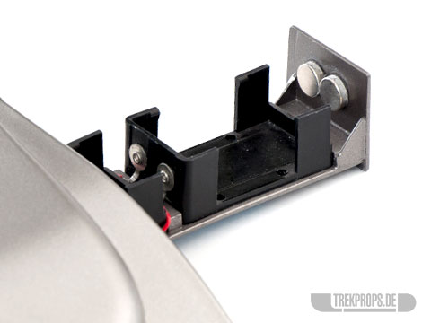
How one is supposed to pull this thing out, you ask? Well, I installed two strong magnets on the inside to be able to slide it out by letting a battery attach itself to the door from the outside and use it as a grip. That way I was able to avoid having to mount some kind of distracting handle on the outside.
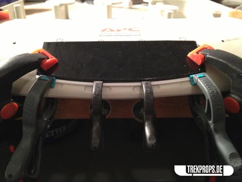
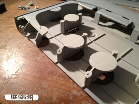
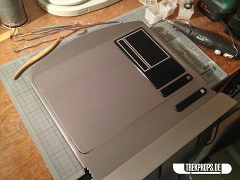
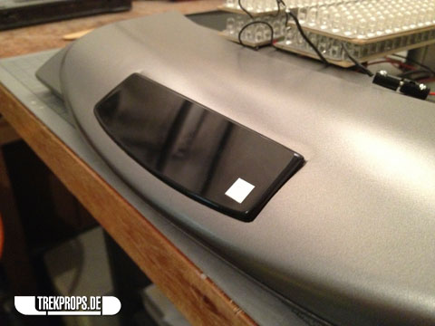
Directing my attention back to the outside of the prop, I then took care of the spot on the front where one of the black acrylic plant-ons was going. Since the “trackpad” part had a flat plane on the back and the body of the base unit had a curvature, there was some filing to do to make it fit:
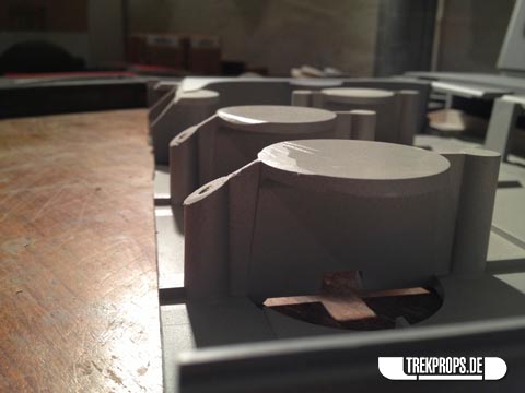
Before:
After:
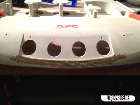
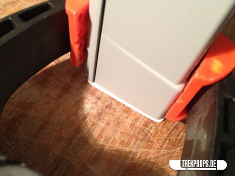
I wanted the “trackpad” to comfortably rest on the base body, so I had to manufacture a lower lip for it to sit on like this:
A thin strip of styrene and a bit of putty did the trick:
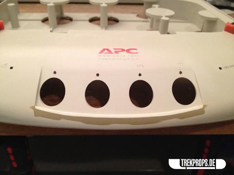
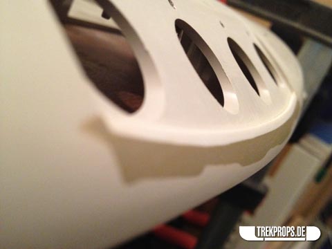
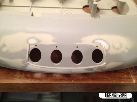
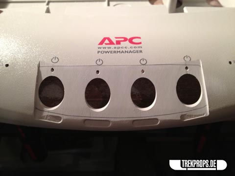
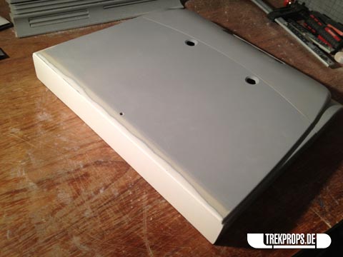
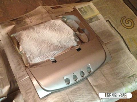
After the usual seemingly infinite game of filling, sanding and priming, the front finally looked how I wanted it to look.
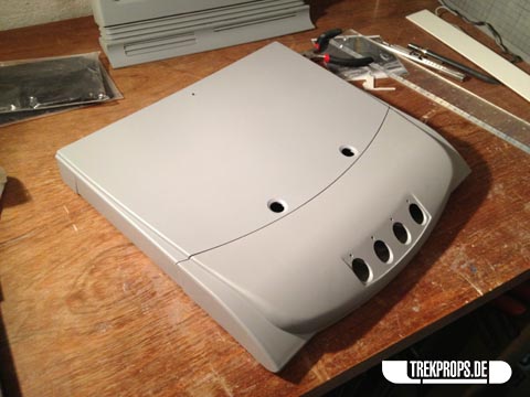
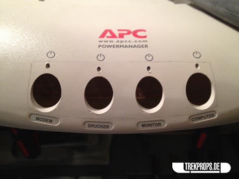
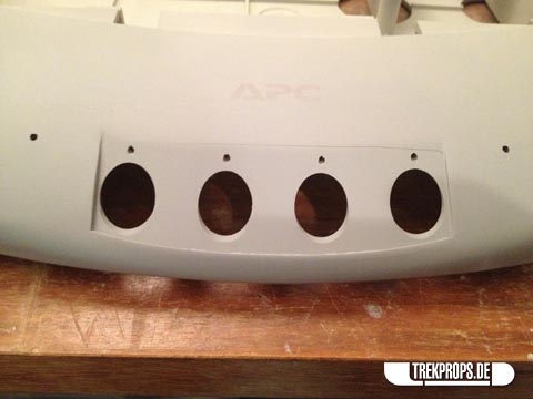
Later I noticed that those small label indents under the knob holes that I filled in were left untouched on the original props, probably due to lack of time. So strictly speaking I went through more trouble than I would’ve had to, but I’m happy with my idealized solution nonetheless.
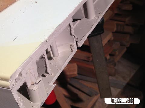
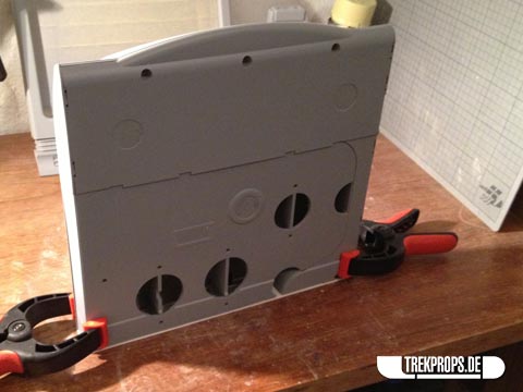
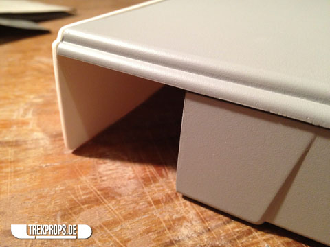
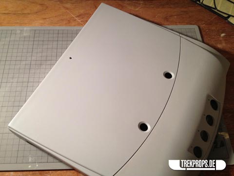
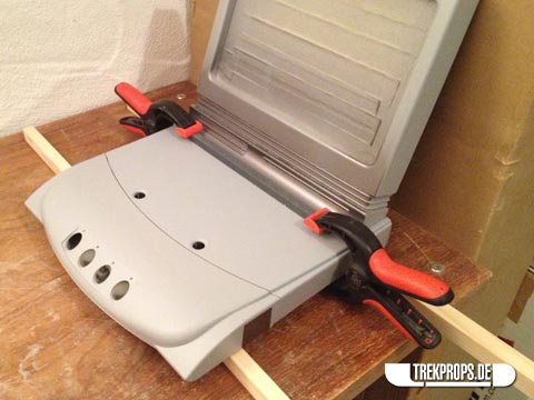
Remember how I shortened the base unit using a circular saw before? Well, now it was time to fabricate a new rear end for it. Here’s how the open end looked after I had thoroughly cleaned it. Note the small hole I drilled into the top. This is where the wires from the power supply in the base are going to go into the screen section.
I used a simple piece of styrene as a new back for the base.
A good fit all around was essential for this piece. After all, I didn’t want it to scrape on the desk every time the computer was moved, so it mustn’t be too tall. But it also had to be large enough so that the backside is completely covered. So I took my time fitting this component until it was just right:
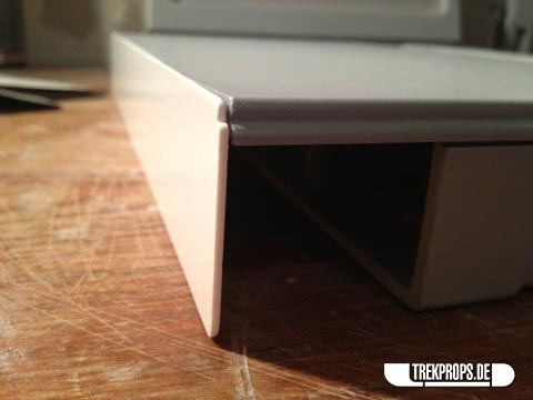
After I had glued it on, it was time for some putty again to fill the seam along the top.
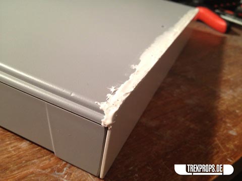
Also, I wanted to reinforce the inside to make it a bit sturdier, so I applied some putty there as well.
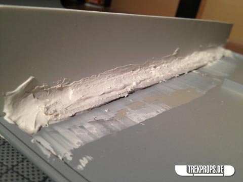
This of course meant that I had to bevel all of the supporting structure inside with a saw to make room for the “putty edge” I created inside the sliding top cover.
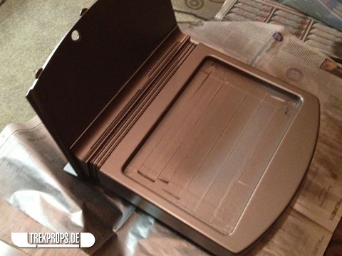
All sanded and primed to the final finish. That’s always the best part. 😉
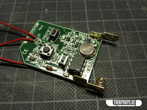
In between I worked on the remote control on and off. Here you can see the board for the transmitter:
And here is the whole circuit installed in one of my ODN Scanner bodies. As you can see it’s pretty simple: The power source, a button, the transmitting circuit, a LED and an antenna. Pressing the button triggers the receiver inside the desktop viewer and activates the display backlight. Nothing too complicated. The building process for the remote wasn’t any different from my usual ODN Scanner builds, except that I had to build a custom holder for the exotic battery this circuit needs and the alternative color scheme I decided to use to set it apart from my standard DS9 version.
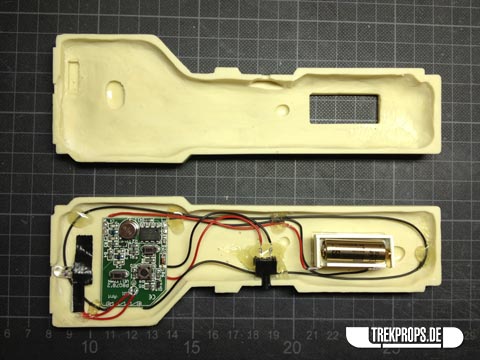
Why a remote control to begin with, you ask? Have a look at my “show-off” post, where I explain it.
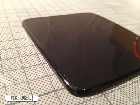
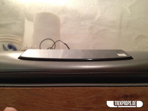
A very special challenge was to get the edges of all the black acrylic pieces (“keyboard”, etc.) rounded and smooth and to make them look as shiny as the the rest of the surface. The crux was that I couldn’t prime/sand/paint these pieces to get rid of any imperfections, which presented a seemingly unsolvable problem:
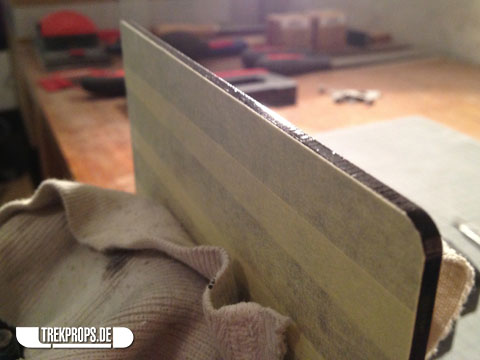
The first step was to round the edges using a file and rough sandpaper. This of course produced an equally rough edge.
Next I used a fine grit sandpaper and wet sanded the crap out of the edge. Afterwards it felt smooth, but still looked frosty and dull and I just wasn’t able to make it shiny using sandpaper alone, no matter how often I went over it.
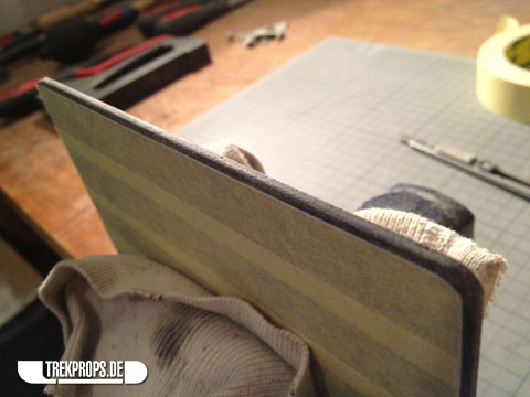
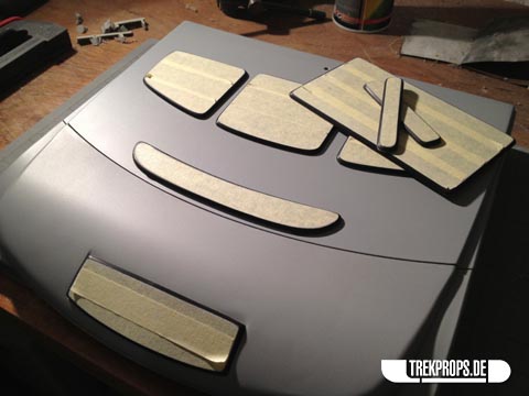
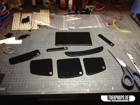
Here you can see all of the parts preliminary treated with sandpaper.

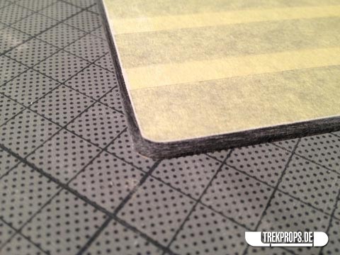
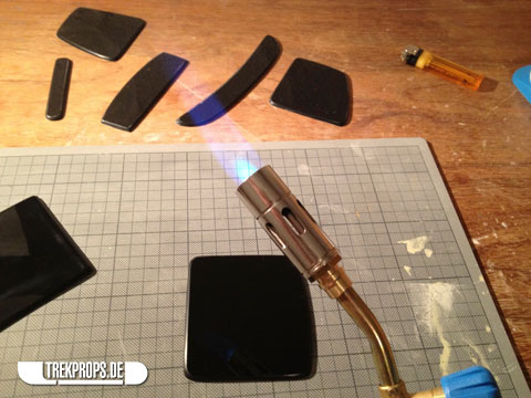
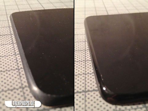
So, how to solve this problem? The solution is a technique called “flame polishing”, where you quickly go over the edge with a butane torch. The heat from the torch partially melts the plastic and the surface tension evens out the surface which makes it look shiny and glassy. It takes a bit of practice, but works very well. Excellent, just what the doctor ordered!
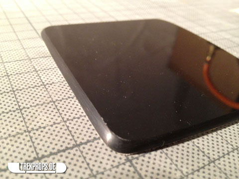
Check out the difference:
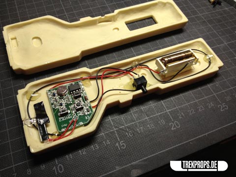
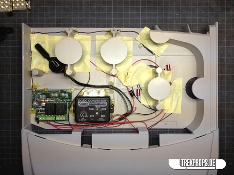
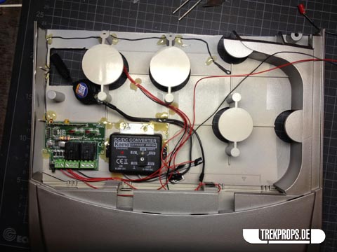
Time to install the electronics into the base body! As you can see here, it really isn’t a lot of stuff: On the left you see the receiver for the remote control, right next to it is the power converter which makes sure that the circuit always gets the same amount of energy, no matter what power source you use (batteries vs. power outlet). I used hot glue to fix everything inside the casing. On the right you can see the battery holder all wired up.
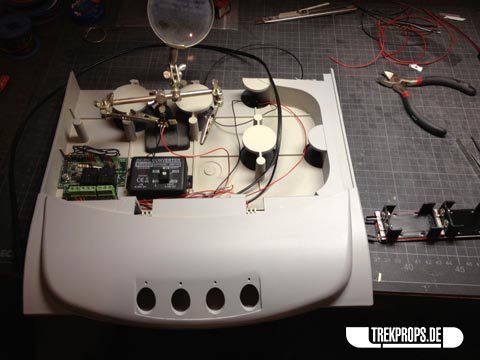
To switch between battery power and mains supply, I installed a switch inside the body. Its normal position is to let the circuit run off the mains adapter. When you trip it, it switches to battery power, bypassing the remote control receiver unit and turning on the backlight at the same time. Since the receiver needs quite a bit of energy to keep “listening” for the trigger signal, it made no sense to keep it active while on battery power. The batteries would have run out of juice too quickly otherwise.
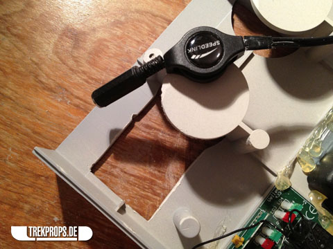
To have access to the power switch and the power cord, I created an opening on the underside of the unit. To get through the thick plastic, I drilled a series of holes first and then cleaned up the jagged edges using a file. To get to the switch and the cord on the inside through this door, you have to lift the whole unit up and tilt it to the side. This is a bit cumbersome, but necessary to make it invisible and a small price to pay in my opinion.
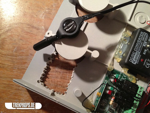
You can also see the cable roll here which lets you unwind the cable and retract it back inside automatically when you’re done. Neat!
Here is the final layout of the components, neatly arranged and masked from the back side in preparation for painting.
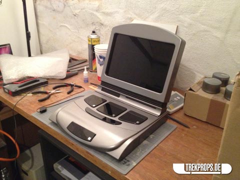
Everything was coming together now. The last big step in construction was to mount the “foot” of the screen onto the top cover of the base unit. Once more I used two-component epoxy glue for a stable bond. The tricky thing is to apply just the right amount of glue so that it is enough to make it sturdy, but keep it from oozing out all over the place.
Masking the electronics prior to painting.
Time to paint! I used a PK 7173 equivalent (MOTIP 51084) to match the standard Starfleet issue metallic grey color.
Be sure to always prop up your parts when you cannot hang them up to avoid ugly marks.

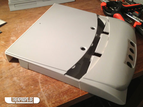
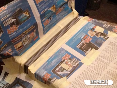
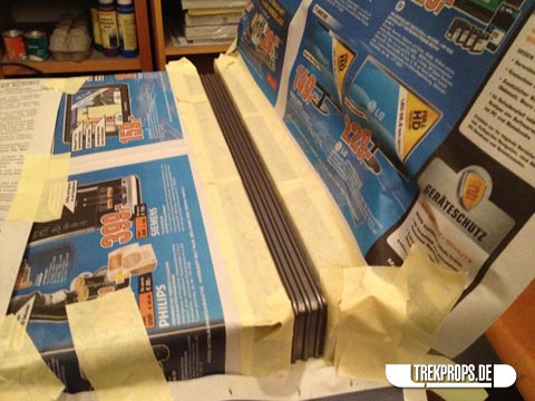
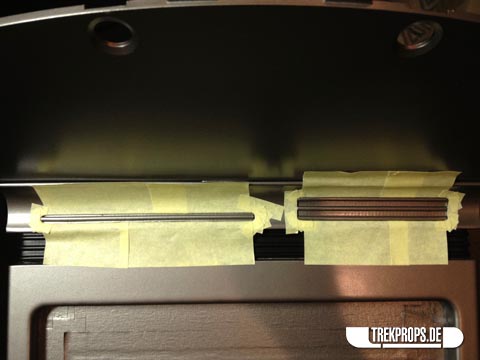
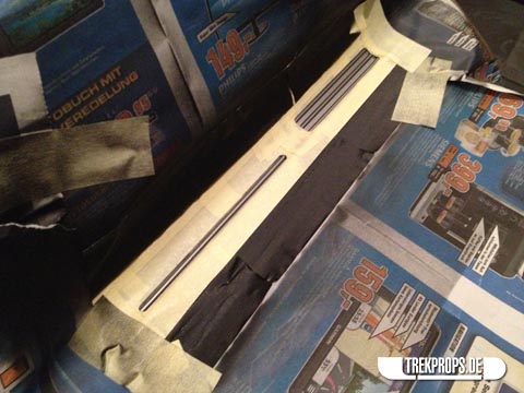
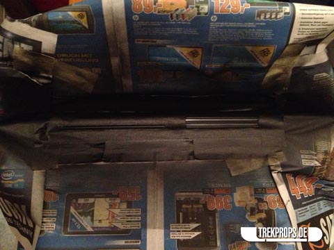
With the base coat on, let’s take care of the details. For the ridges under the screen I used a matte black color for a cool look. Notice how I use masking tape for intricate masking and newspaper pages to cover large areas.
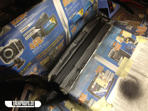
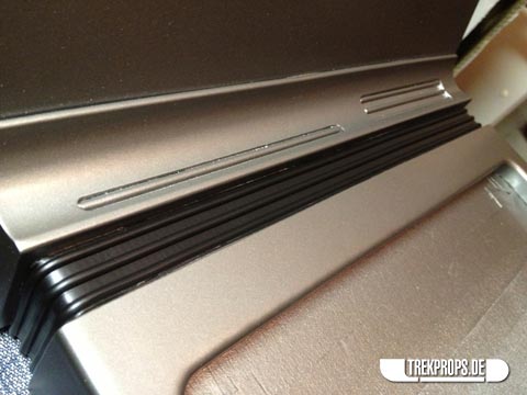
Masking tape removed. Nice!
On to the details. To give the black plant-ons the final touch I used chrome adhesive foil for the decals.
Here you can see the magnets being inserted into the back cover frame using epoxy and hot glue:

The LED boards were hot glued on to the inside of the back cover.
Fits like a glove! 🙂
Here’s the inside of the main body again, with all the masking tape removed. Note how I neatly I arranged all the wires inside. The black one running along the left and top side is the antenna of the remote control receiver.
The last step was to glue the remaining plant-ons on to the unit:
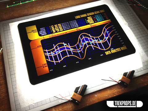
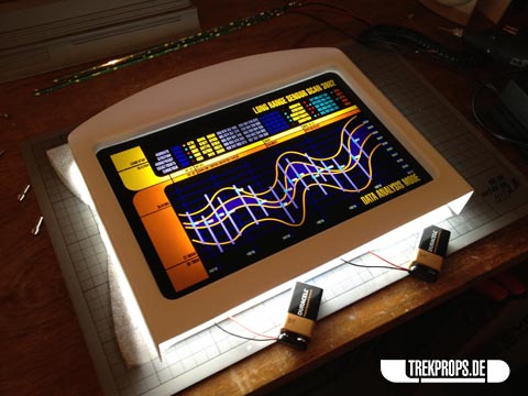
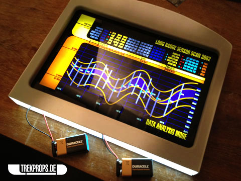
And voilà, all done! Here she is in all her glory:
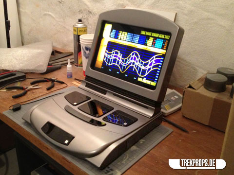
For more pictures of the finished prop, check out my “showcase” post. If you have any questions, feel free to leave a comment below or to drop me a line at info@trekprops.de. You can also follow me on Twitter (@trekprops) if you like.

4 Responses to “Work in Progress: Voyager Desktop Computer”
Voyager Desktop Computer on: August 9th, 2013 at 20:49
[…] As mentioned above, the alternative to the batteries is a power cord that goes into the wall and keeps the unit running indefinitely, at least within certain limits. The cord is also hidden inside the base unit and can be pulled out, unwinding from a small retractable cable roll. When you’re done, you just let it slide back inside. I have not pictured it here, but you’ll be able to see it among the wip pictures. […]
Sart Trek Voyager Desktop Computer and Remote on: August 10th, 2013 at 15:35
[…] has gone so far above and beyond with this prop build, they might as well be on the voyager itself. As you can see in the selected photos below […]
Voyager Desktop Computer « adafruit industries blog on: August 13th, 2013 at 13:37
[…] Work in Progress: Voyager Desktop Computer via The Grue. […]
Mike on: February 9th, 2019 at 06:43
So beautiful!!! How can I purchase one of these? Thanks
Post a Comment
Want to see your picture next to your comment? Go get a Gravatar!