Tutorial: ODN Scanner Kit Assembly
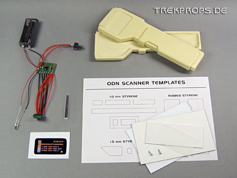
 Welcome to the online assembly instructions for my ODN scanner hero kit. In this tutorial, you’ll see how to prepare the electronics for installation and how to insert them into the body. You’ll also learn how to prepare and assemble the hollow resin shells to build up a fully functional hero ODN scanner. First, here’s a pic of the entire kit: 2 resin body parts, electronics, acrylic rod, display graphics, styrene (1.0 mm and 1.5 mm), 2 screws, templates for the styrene details. That’s all you need, so let’s begin!
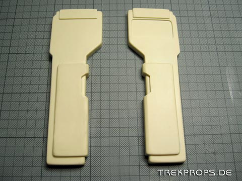
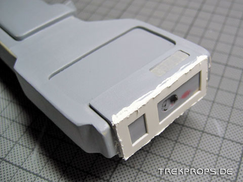
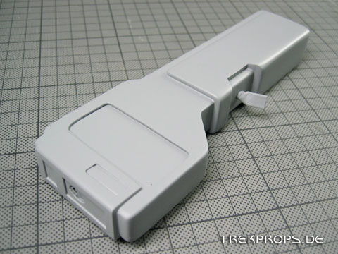
Here’s a closer look to the resin parts that come with the kit:
First up: Wash these parts in warm, soapy water to get rid of any mold release agent that might still be sticking to them. You need to get it off completely because it can prevent primer and paint from adhering to the surface properly.
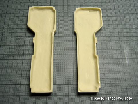
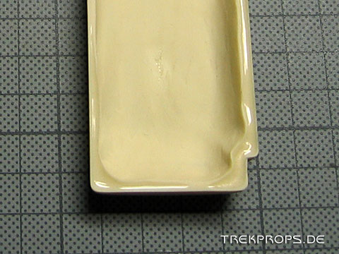
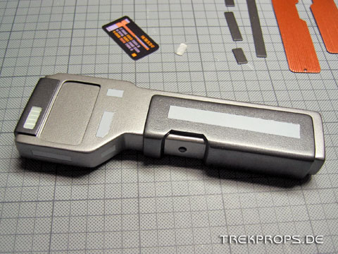
Parts cast in resin are most times rough when they come out of the mold and have to be sanded smooth before processed further. In this case, the pouring of the resin created a ridge in the “walls” of the body shell. This is the area that will later be glued together. Here’s a close-up:
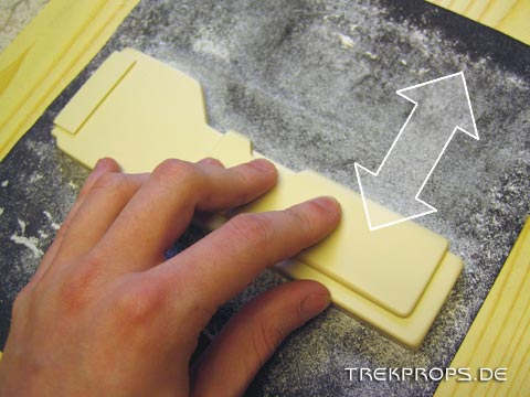
In order to make it possible to glue the parts together, you have to sand those areas smooth. I use a large piece of sandpaper mounted on a board to accomplish this.
The parts that come with the kit have already been pre-sanded, but you’ll still have to do some fine-tuning to fit the parts together perfectly.
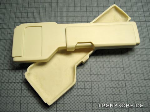
Be careful not to sand too much material away – keep in mind that the electronics have to fit inside! Keep measuring the thickness of the two shells aligned to each other with a Caliper to make sure the prop will be equally thick on each corner.
Here’s the result:
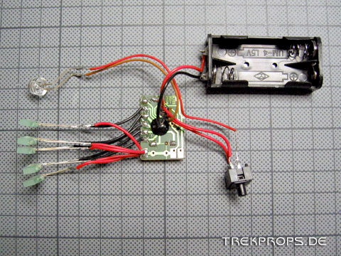
Before continuing with the body, let’s pay some attention to the inner workings of the scanner first! Here are the electronics that are included in the kit:
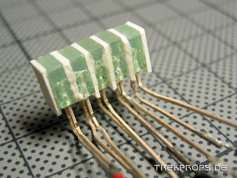
Since the LEDs alone are not wide enough when placed next to each other, use some 1.0 mm styrene to act as spacers between them. This way, the width will be more accurate to the original prop.
This step can be quite tricky! Use some fast setting super glue and rough up the LEDs as well as the styrene with sandpaper or a file. When done, the glue will bond easier to the material.
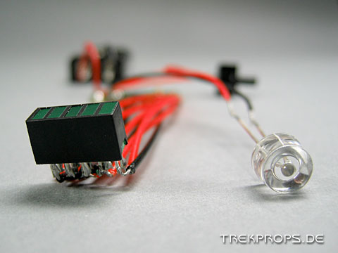
Update: Since I wrote this tutorial, I’ve improved the set of electronics and am now using a LED bar instead of five seperate LEDs. Thereby the aforementioned (very elaborate) step in construction can be dropped:
Also, I am now using other super-bright red LEDs as the one shown here.
Next you’ll have to cut out all the windows out of the resin parts. Let’s start with the one for the front LEDs. As you can see in Part II, I specifically designed the silicone mold to create a particularly thin layer of resin in this area. That way this step is easily done with a sharp X-Acto knife.
Although the area of thin resin is fairly large, be sure not to create a window that is too big, because you wouldn’t want to have any gaps later. Keep comparing your assembled LED bar with the window to ensure a tight fit. Of course, if you want a bigger window, feel free to do whatever you think looks best. Gaps can be filled with putty later if needed.
Use a small jewelers file to smooth the edges. If necessary, use some spot putty to resculpt any imperfections here. Primer the part to reveal any blemishes and keep working until they are removed. When the electronics are installed, any work on this window will be very difficult, so complete it before the installation!
Next you need to cut out the battery door. The best place for it is in the handle on the backside of the prop. The opening can be conveniently hidden under one of the styrene parts that will be added later.
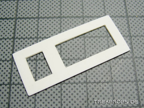
To determine the dimensions of the opening, simply measure the battery holder which is included with the kit. Then, cut out the matching styrene part using the included templates and place it on the handle.
Hint: Use spray glue to attach the templates to the styrene before cutting. This way the shape will be accurate and the paper can be easily removed in warm water.
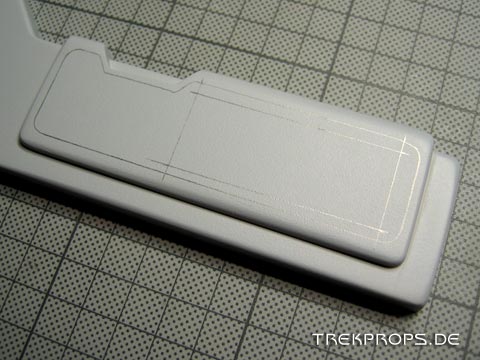
Trace the outline of the detail piece and add the measurements of the battery holder like this:
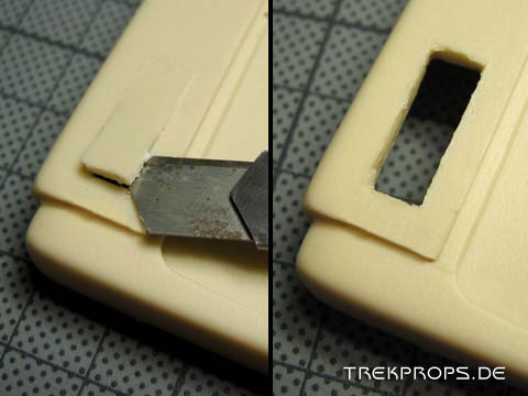
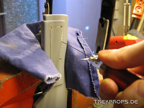
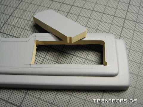
The resin in the handle is approximately 5 mm thick, so you’ll need something more effective than an X-Acto knife this time. You can get good results if you drill four holes in the corners of the layout and then use a fretsaw to cut out the door.
This is the result.
Use a small and flat file to clean the shape of the door.
Now, the openings for both the trigger and the top LED have to be drilled. When doing that, it’s important to align the resin halves perfectly and to be careful not to bring them out of alignment during the drilling process.
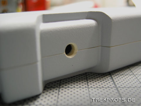
For the trigger, simply drill a hole of 4 mm in diameter in the middle of the recessed area on the handle. Test fit the trigger and extend the orifice if necessary before continuing!
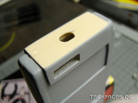
To determine the location of the opening for the top LED, use the template of the head piece, which will be added later. You can also use this and other pictures in this tutorial as a reference.
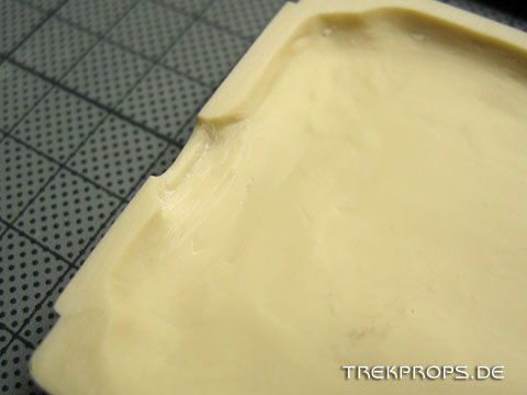
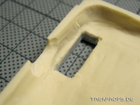
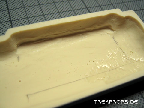
You’ll have to make sure that the electronic components have enough room inside the body to perform their function. To do this, you’ll need to dremel some of the material away.
This is where the battery holder will be put. You’ll have to align it to the door in the other body half, which will be placed on top of this one to enable easy access to the batteries. Again, use the dremel to create some more room if necessary.
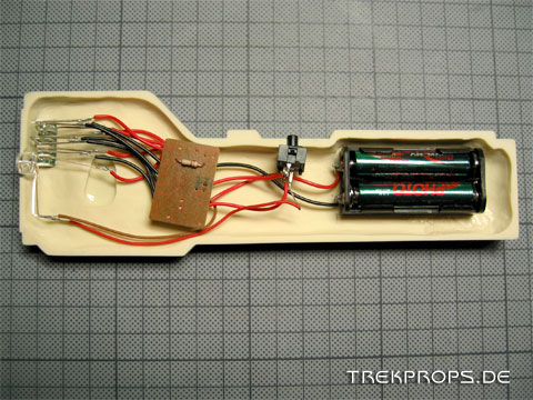
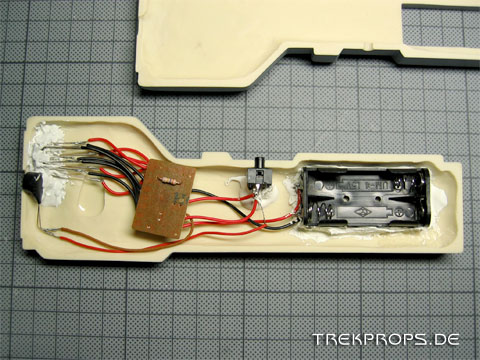
This is how the electronics are arranged inside the prop:
To attach all of the components permanently into the resin shell, use a strong putty, for example a 2-component polyester putty which I use in my builds.
As you can see, all of the LED components are placed very near to each another. In case of the green running lights, this is on purpose and not a problem. But as far as the super-bright red LED is concerned, there is a problem with the close proximity to the green LEDs: Light bleeding. To make sure that the red LED doesn’t light up the green ones next to it when activated, you’ll have to putty up the entire area around the green LEDs and use black masking tape around the red LED.
When inserting the LEDs into the window, be sure not to make them flush with the front of the resin body. There needs to be some space for a piece of the included translucent plastic to go in there later.
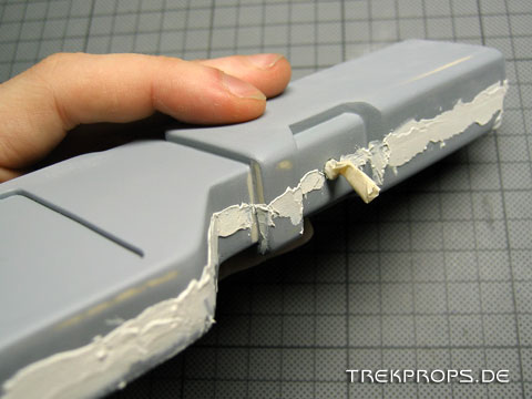
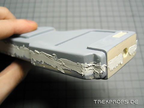
When the electronics have been successfully installed and tested, the resin body can be permanently sealed. First, use 5 minute epoxy glue to attach the resin body halves to each other. Then, putty up the seam lines and sand them smooth when the putty has dried.
This is the most elaborate part of the buildup. Use primer to reveal any blemishes in the finish and remove them with spot putty and sandpaper until they’re all gone. Be sure to mask all LEDs and the trigger to protect them from sanding, puttying and priming!
Next, the head piece needs to be attached. Before you do that, sand a good portion of the top array off so that it will have the original thickness afterwards when the styrene is in place. Use the templates to cut out the shape and then use 5-minute epoxy to glue it on.
Again, putty the edges and use sandpaper to round them. Try to make it look as if the part was integrated into the overall shape of the prop from the beginning. As before, repeat the puttying, sanding and priming until the result is acceptable.
When everything is done, it’s time to paint!
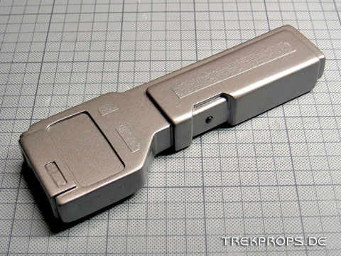
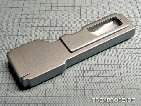
You don’t want to glue the greeblies onto the paint later, so mask off all areas which will be enhanced with details. Then, paint the entire body with PK 7173 or a matching equivalent.
Don’t forget to drill the holes for the battery door screws!
When the paint has fully dried, mask off everything but the handle and the top scanner array and paint them with PK 7179 or a matching equivalent.
After this is done, remove the masking tape and continue with the last step.
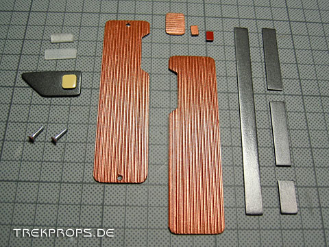
Here all of the detail parts at a glance. For the emitter, shorten the acrylic rod to a length of approximately 12 mm and cut it in half. Sand the flat side of it to achieve a frosted look and a light diffusion effect.
Here are the color codes for the greeblies: Handle details, front ribbed piece and one of the small top details: copper metallic. The other small top detail: red. Rim strips and pointed front detail: PK 7179 or matching equivalent. Square additional detail on pointed front piece: beige. If you want, you can also paint the screws in the same color as the handle details to blend them in.
Again, use 5-minute epoxy or CA glue to attach the greeblies.
Screw the battery door in place after inserting two AAA batteries.
Fit the translucent plastic into the front LED window and insert it.
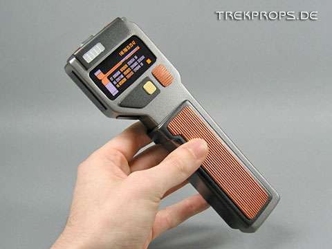
Cut out the display graphics that you wish to use and test fit them. When your display graphic fits the recess perfectly, use some thin double-sided adhesive tape to glue it inside. You can also use spray glue for this.
That’s it, your ODN Scanner is finished!
Now, go ahead and scan away! 🙂



20 Responses to “Tutorial: ODN Scanner Kit Assembly”
John Cuddeback on: December 6th, 2009 at 18:41
Hi there I was wondering if you sell the ODS scanner kit?? If so how much? you can always reach me at the email I have put in here in the required field. Thank you very much for your time .
Sincerely,
John Cuddeback
trekprops.de on: December 6th, 2009 at 18:51
Hi John, I sent you an eMail! 🙂
Michael on: March 21st, 2011 at 21:11
I received this amazing kit in January and it took me about 6 week to finish it. Thanks to that exceptionally well written and illustrated tutorial it was no big deal and I’m very satisfied with the result!
Trekprops is reliable and most courteous – the whole deal was immaculate!
Thanks trekprops!
Patrick on: March 26th, 2013 at 17:11
I would LOVE to get one of these scanner kits. Please send me an email with price and payment method! Thanks!
Ryan on: May 21st, 2013 at 09:05
I’ll second Patrick’s sentiment. If you have any of these kits still available, please do let me know. 🙂
Marvin on: June 22nd, 2013 at 16:37
I´m also interested in this Prop. Could you tell me where you get the Kit Assembly.
trekprops.de on: June 22nd, 2013 at 17:00
E-Mail sent! 🙂
Work in Progress: Voyager Desktop Computer on: August 8th, 2013 at 22:55
[…] Nothing too complicated. The building process for the remote wasn’t any different from my usual ODN Scanner builds, except that I had to build a custom holder for the exotic battery this circuit needs and the […]
peter bosmans on: October 15th, 2013 at 19:28
hi there i was wondering if you sell me two ODN scanner kit’s.
eletronics not included, only the boy parts.
i can pay you with paypal.
thanks, end mail me back.
Golthem on: October 16th, 2013 at 23:22
Hello! I was wondering if you could give me an estimate on how much a kit would cost…
trekprops.de on: October 17th, 2013 at 21:29
@Peter Bosmans: Sorry, I tried to send you an E-Mail, but it didn’t go through. If you read this, please send me an E-Mail to info@trekprops.de. Thanks!
@Golthem: E-Mail sent! 🙂
Steve on: December 30th, 2013 at 23:41
Hi there I’ve just aquired a canovision camera case that was used for O’brian’s tool kit and im desperate to fill it, I wondered if these odn scanners are still available and where from?
Thank for any help!
Jake on: March 30th, 2014 at 05:44
Hey, I am definitely interested in one of these kits. They still available?
trekprops.de on: March 30th, 2014 at 15:46
@Jake: E-Mail sent. 🙂
Marco on: June 14th, 2014 at 00:12
Hallo,
ich wäre interessiert an so einem Bausatz. Kannst Du mir vielleicht sagen wie ich daran komme? 🙂
trekprops.de on: June 16th, 2014 at 08:41
E-Mail ist raus! 🙂
Jeremy Norman on: December 14th, 2014 at 22:52
Hello,
Wondering if a kit is available to buy?
Thank You
Sbastable83 on: July 1st, 2015 at 23:48
Wow what a great prop do you have any of the kits available to buy?
Jack Hayes on: October 29th, 2015 at 20:58
Hello, is this kit still available? if so, please let me how to make payment and ship ASAP! Thank you very much
John on: December 26th, 2019 at 18:17
Wondering if you might still have a kit available after all these years. I’d be interested.
John
Post a Comment
Want to see your picture next to your comment? Go get a Gravatar!