Work in Progress: Neutrino Probe – Molding
If you want to make more than one unit of any given prop replica, it is inevitable to make molds of all the parts you need. This way you’ll be able to make multiple resin casts of each piece. For the Neutrino Probe, this presented a few unique challenges I had to tackle along the way due to the special nature of the body, its prototype parts and the fact that I wanted to put electronics in there. In this blog post I’ll show you exactly what I thought would work, what did’t work and – most importantly – what I ended up doing.
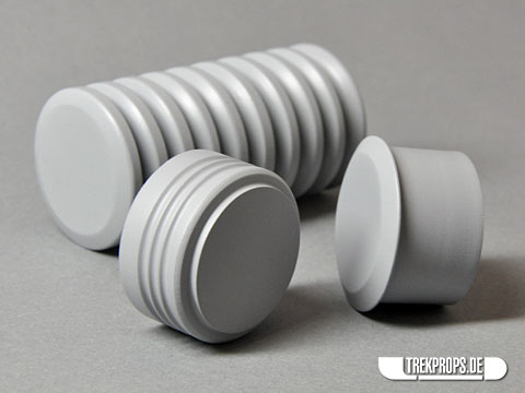
If you remember, the main body of the Neutrino Probe (minus the emitter) consists of five pieces – some of them big and some of them rather small.
Let’s begin with the main piece, which was the trickiest to mold. Why was it so tricky?
Well, for one it had to be hollow for me to be able to install the electronics later. To do that I needed enough room inside to fit the circuit in. However, due to the large grooves on the outside it was difficult to estimate how much I could hollow out without risking to break through one of the grooves. Therefore everything had to be measured exactly.
The other aspect was that the master model for the main part obviously was round since I turned it from wood. The actual prop part however needed to have one flat side where the display panel would go. How should I approach this? Cut off the unwanted piece before molding? No. Being out of wood, the material could easily have ripped thus ruining the entire thing. Also, being round it would’ve been difficult to get a grip on it and make a clean cut. Lastly, it would have been too final a solution for my taste. Had I cut off too much of it, I would’ve had no way to correct that mistake. So, I decided to solve the problem by molding only as much of the prototype as I needed and not one millimeter more. I’ll explain below.
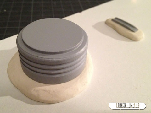
To be able to do precise work, the first thing I did was to mark a line on the prototype where I wanted the flat side to be:
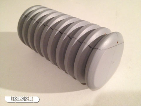
My first idea was to suspend the piece in silicone rubber by hanging it from wires (that’s what the small holes in the picture above are for) and pouring rubber in the mold below, until the pencil line was reached. What I didn’t take into consideration however, was that wood actually floats, not only on water but also on silicone rubber. Duh! So when I poured the silicone inside the mold and it reached the master model, it slowly began to move upwards, sinking my plan (pun intended ;)) millimeter by millimeter.
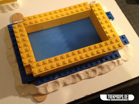
So, I needed a new plan. And one was quickly found. It was slightly more elaborate, but worked perfectly. Here’s what I did:
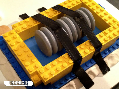
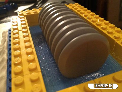
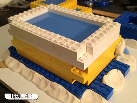
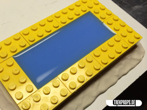
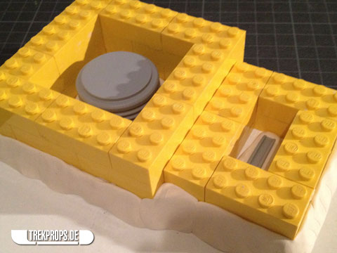
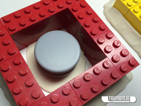
Since molding only part of the master model didn’t work, I decided to do a full-blown two-part mold with a lid that I could later take off. And that lid should be exactly where the pencil line was. The first step to accomplish this was to use a scrap piece of cured silicone from the first try and use it as the “floor” for the new mold box. Yes, you can saw cured rubber quite well. On top of that I built the box walls using LEGO as I always do. Around that I put some plasticine to seal the box and fix it in place.
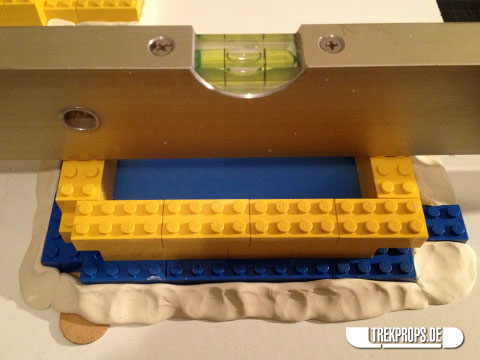
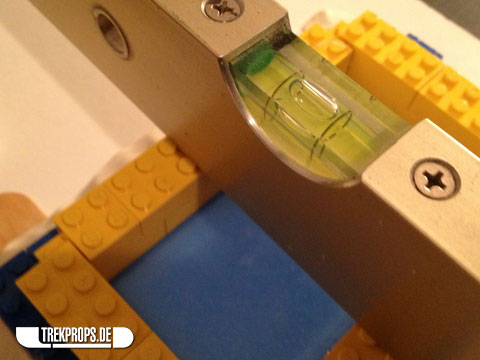
Having everything absolutely level is important if you don’t want to produce crooked castings. That’s why I always check using a water level before molding.
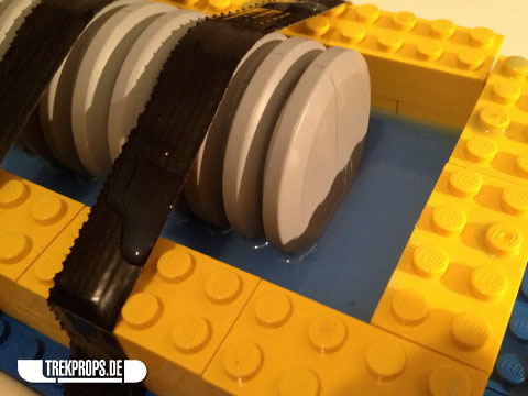
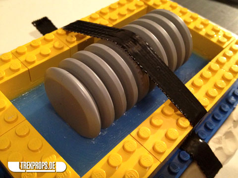
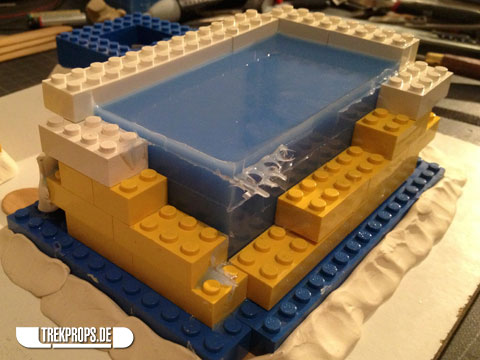
Next I placed the prototype part inside the mold box and secured it using two strips of tape. Any type will do. I arranged it in such a way that the pencil line on the body was parallel to the “floor” of the mold box.
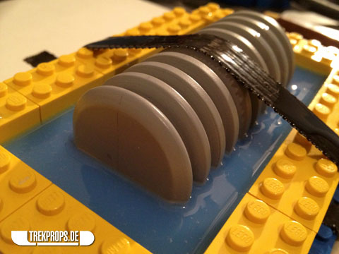
I then poured a little bit of silicone in the box, just enough so that the master model was covered up to the pencil line.
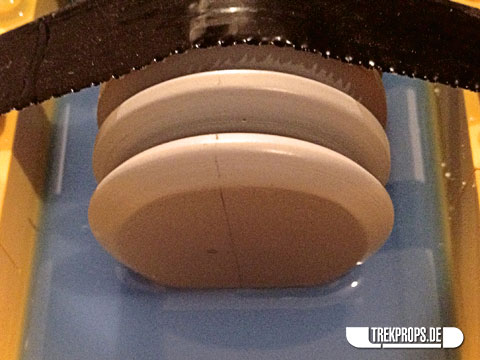
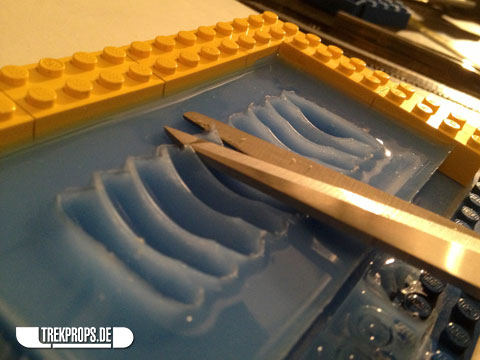
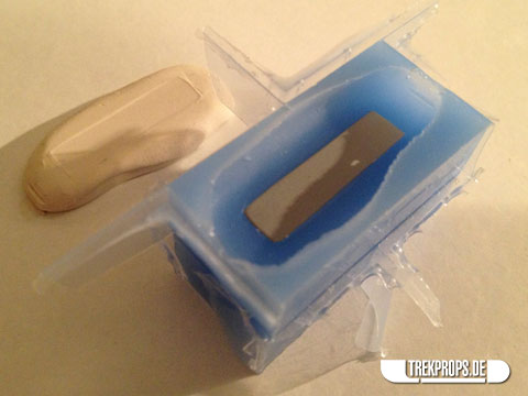
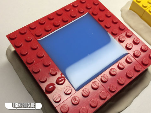
And this is how the silicone looked like when it was cured. This was gonna be my lid.
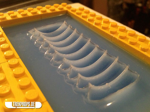
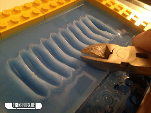
In order to continue, I then had to clean up the lid a little in an effort to make it as flat as possible. So I removed the excess rubber using scissors…
… as well as cutting pliers.
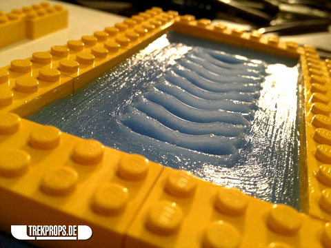
As preparation for the next step I then applied (quite a lot of) vaseline on the exposed area of the silicone as a releasing agent.
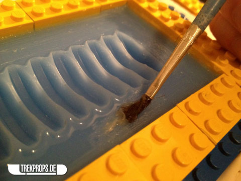
In this next image you can clearly see the applied vaseline and the brush strokes on it.
Then I reinserted the master model inside the mold…
… and secured it again using tape to prevent it from floating up as it did before.
Then I poured in silicone once more.
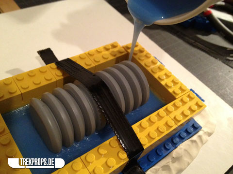
Note that I only covered the piece by about half. Why? Well, I couldn’t leave the tape in there to keep the prototype in place, so I needed something else. That’s what this intermediate layer of silicone was for.
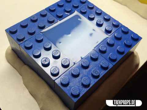
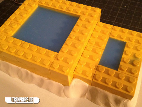
When it cured it acted as a grip to keep the part where it was supposed to be and I could extend the box walls (the white LEGO pieces in the next picture) and fill up the mold. Without any vaseline in between, the silicone became one piece in the end, which is exactly what I wanted.
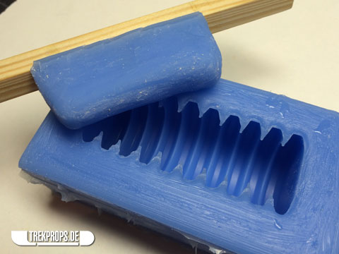
After demolding I was able to seperate the two pieces of the mold without any problems.
Getting the master model out of the mold was a little tricky, since so much of its round form was inside the mold, but thanks to the flexible nature of silicone rubber that became no serious problem.

After a little cleanup I was very happy with the result:
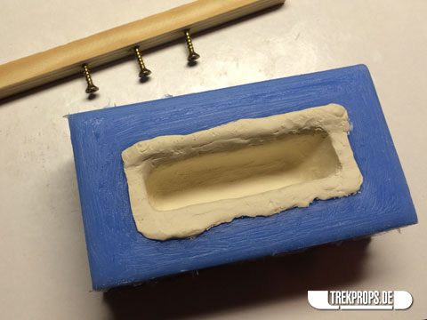
Now on to the next challenge: Making the casting hollow. Since my “resin displacement”-technique worked so well with the ODN Scanner, I didn’t think twice to use this method again here. The idea is to manufacture a rubber displacer piece on a stick that can be lowered down into the mold before filling it with resin. Afterwards it can be removed, making the final piece hollow.
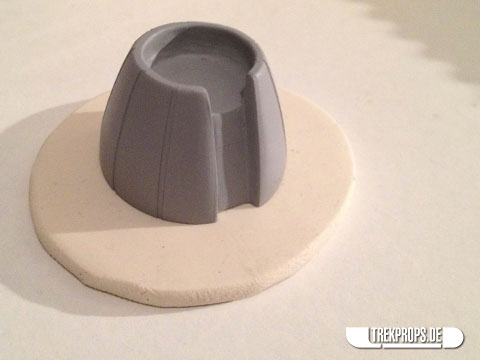
To create this rubber displacer, I prepared a wooden beam with three screws, only partially screwed into the handle. This is where the rubber would stick to the grip. Inside the mold I used some of the clay that I use to prevent mold boxes from leaking to form a temporary mold for the displacer. The tricky thing here was to estimate how thick the walls and how big the displacer should be. I ended up making the mold rather large, thinking that I could always remove some of the cured silicone from the displacer piece to make it smaller. No correction would have been possible in the other direction.
(By the way, that’s what I ended up doing – shaping and correcting the cured rubber by cutting and sanding away material until it was just right.)
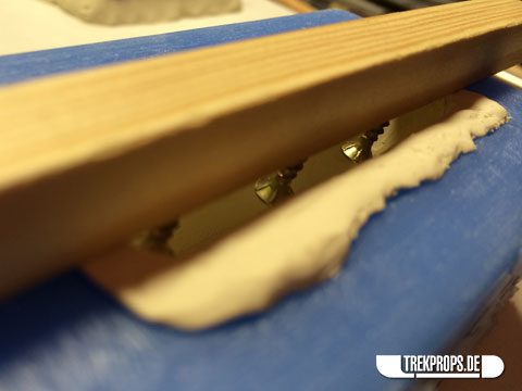
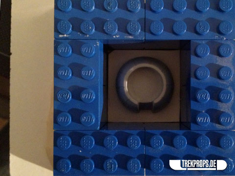
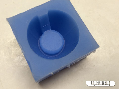
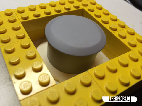
This is how the displacer grip looks like lowered down into the mold.
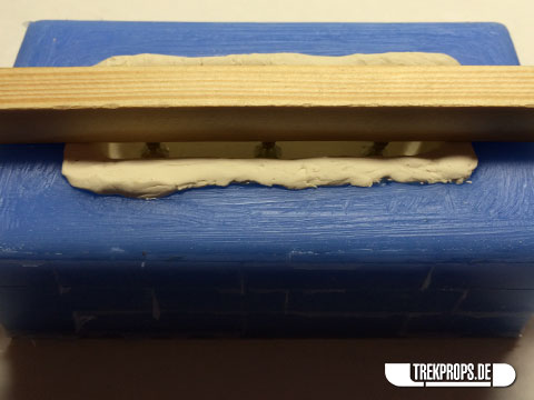
In this shot you can clearly see the screws that will dip into the silicone and attach the displacer to the wooden stick.
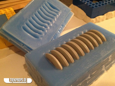
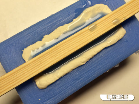
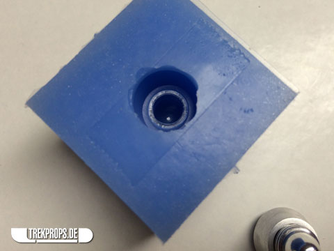
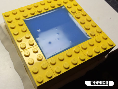
All filled up with some RTV rubber:
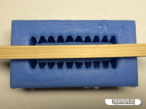
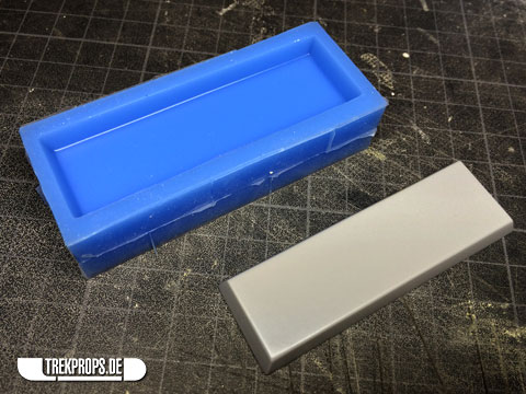
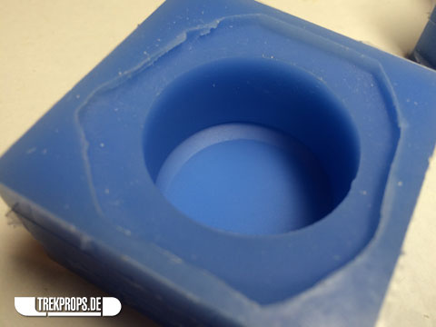
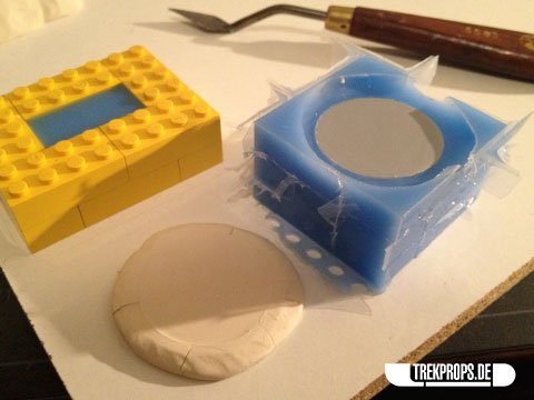
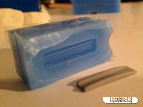
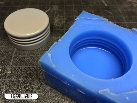
And this is how the complete mold looks like after demolding and cleaning up:
A perfect fit! 🙂
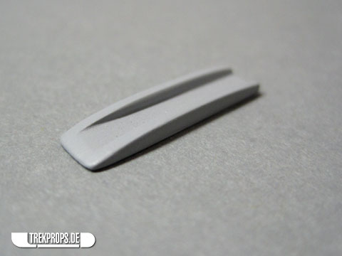
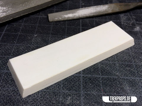
Now, if you have paid attention, then you know that the very first sentence of this post after the break actually isn’t correct. The main body of the Neutrino Probe (minus the emitter) isn’t made up of five, but of six pieces. The sixth very important piece is the display panel, which closes the main body and houses the 7-segment-LEDs for the readout. I built it from three layers of sheet styrene, glued together and filed to shape.
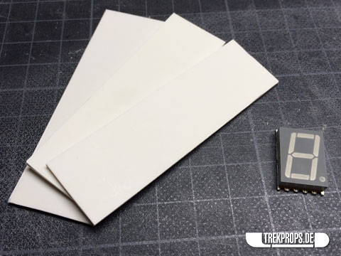
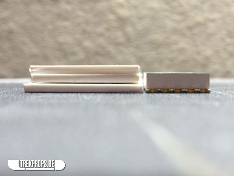
Slightly thicker than the LED component I’m using. Why that is? You’ll see… in the next blog post.
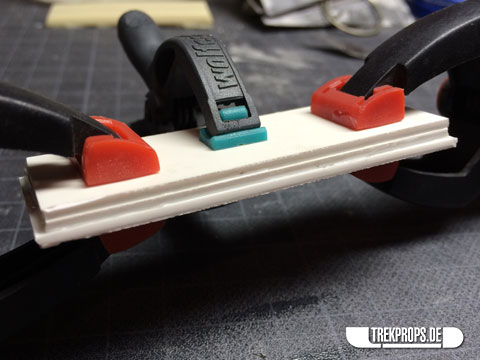
Three layers of sheet styrene glued together.
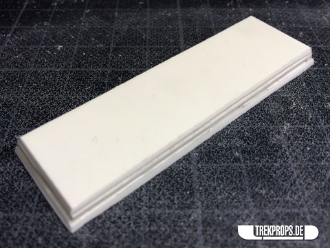
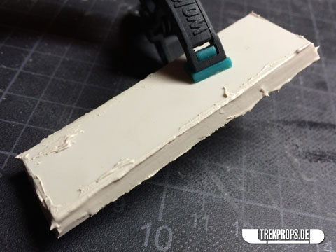
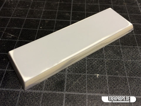
The usual game: File, putty, sand, prime, sand, prime, and so on…
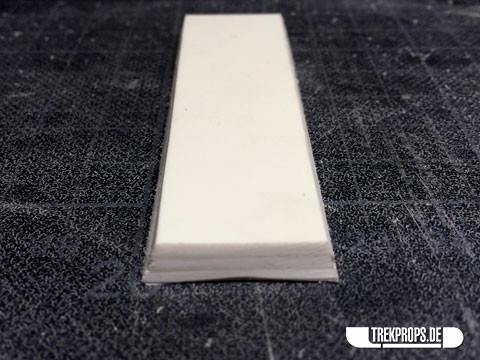
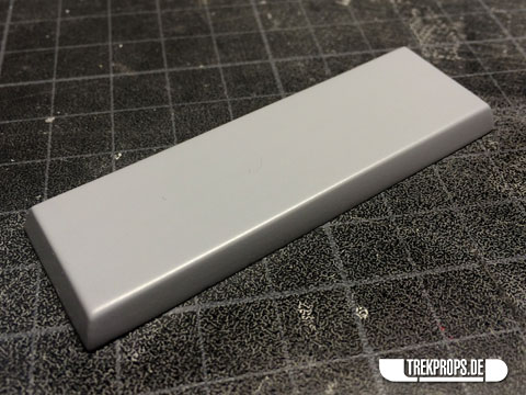
And here’s the finished panel. So why didn’t I build this piece earlier? Well, simple: I didn’t know the exact dimensions I needed before molding the main body element of the probe where this part needed to fit on. So, logically, I couldn’t build it until the mold for the main body part was done.
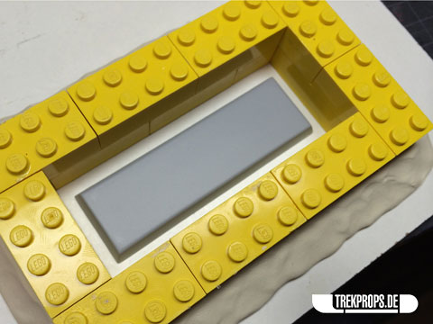
Molding-wise this piece was very easy. I attached it to a board, built the usual mold box around it, and filled it with rubber.
And the finished mold:
Now if you’re thinking “Wait a minute, aren’t those LED digits supposed to be installed into that element? Don’t you need a hole in there for them?”, then you’re thinking right. I’m going to show you how I’m doing that in the next blog post!
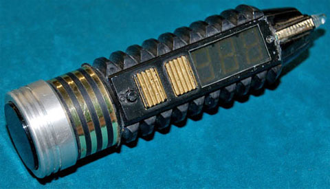
The next piece to mold with an interesting story is the emitter. As you might remember from this blog post, I built one using styrene, putty and primer way back after I did the main parts of the probe. It consisted of two very small pieces and looked like this:
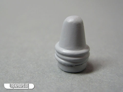
And here it is together with the rest of the business end:
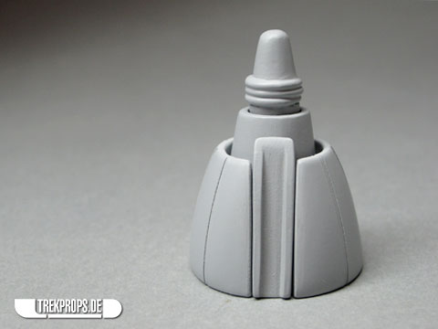
It looked very nice and I was quite happy with my work considering that these pieces are so tiny.
However, I came to realize that they were not precise enough and more importantly not smooth enough. Because here’s the deal: Of course the emitter had to be cast in clear resin so that it could be illuminated from the back. For the casting to be absolutely transparent and clear, two conditions had to be met: The casting had to be bubble-free (more on that in the next blog post) and the surface of the prototype had to be absolutely, 100% smooth. If it hadn’t, the silicone would’ve translated all the irregularity, texture and roughness – as subtle as it might have been – into the mold which would’ve produced castings with a milky, frosted surface and not a glass-like bright finish.
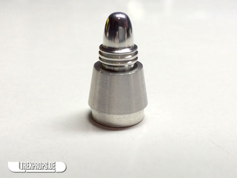
So I reached out to fellow prop-builder Myron Stapleton who has both the experience and the equipment to turn parts from aluminum to measure. I prepared some very detailed specs for him and what I got back matched those dimensions exactly:
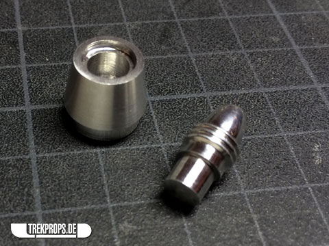
I couldn’t believe the accuracy with wich Myron replicated my diagrams. This is truly the work of a master. Thank you so much, Myron! 🙂
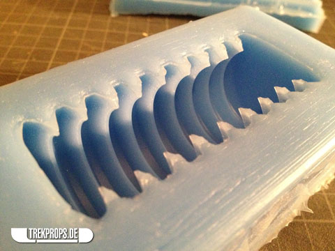
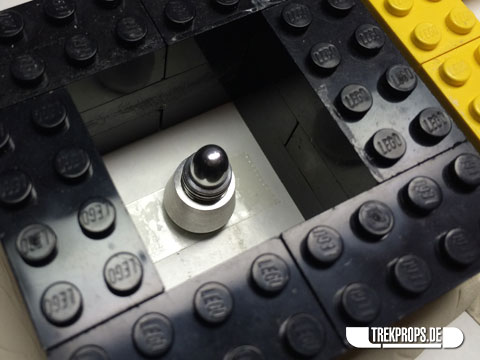
The molding process for this piece was no different than the rest: Put it on a board in a mold box and fill it up with silicone. The one thing I had to be careful with was the speed with which I poured the rubber inside the mold. Pouring in a thin stream I carefully filled the box, paying close attention not to trap any air bubbles while covering all those ridges and crevices.
And here’s the final mold. While molding all the other pieces, I actually made a number of emitter molds so that I could later make several castings at once.
Molding the rest of the pieces was very straight forward. By now you know the drill, so I’m not going to repeat it once more. Just enjoy the pictures:
You’ll notice here that I sometimes used clay as a base for the pieces. The plasticine acted as a light adhesive and also prevented the silicone from creeping under the prototypes thus creating a thin rubber film which can make the demolding process problematic.
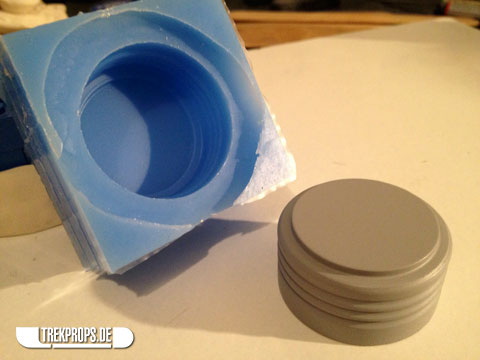
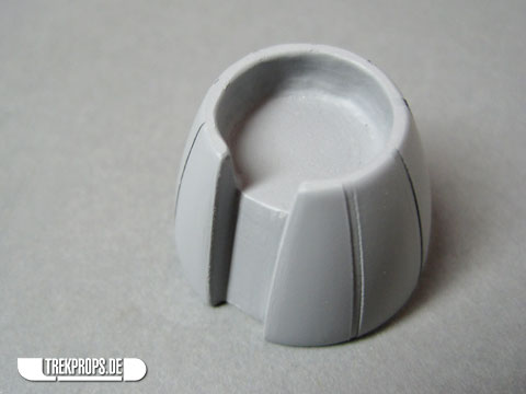
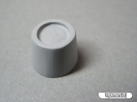
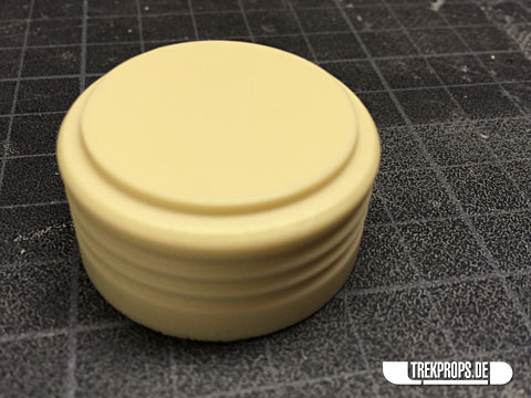
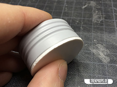
Looking at this last piece, which is the “end cap” of the Neutrino Probe, I realized that painting – or more precisely masking – this component would be quite elaborate since the disc at the top has a different color than the rest. Have a look at the original to see what I mean:
So I decided in the last minute not to include the back disc in the actual “end cap” casting, but to add it later and use the real deal (more on that in an upcoming blog post).
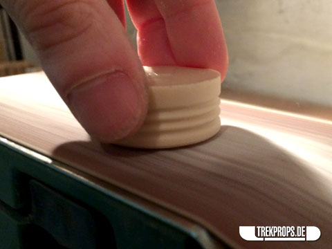
Instead of removing the disc from my original master model (the one which I turned from wood here), I used a resin casting of said master model to preserve the original.
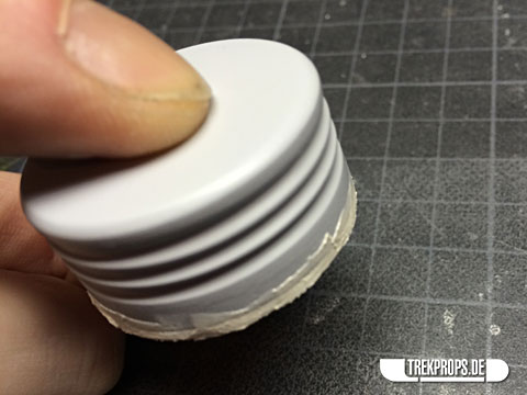
If something had gone wrong, I simply had made another pull from the mold and started over. But, thankfully, there were no problems. First, I shaved off the majority of the top disc using my belt sander like this:
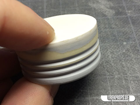
Then I used sandpaper stapled to a board to gently remove the rest. Wet sanding makes for a smoother surface.
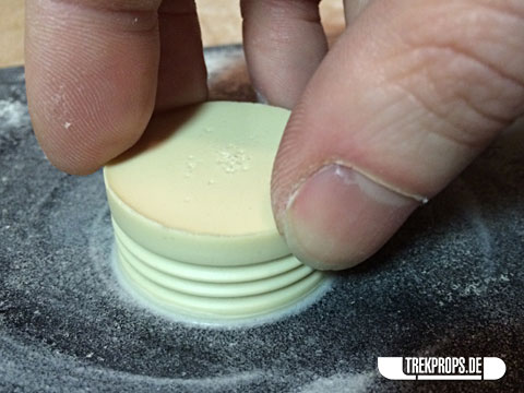
After some priming and more sanding, the surface was perfectly smooth.
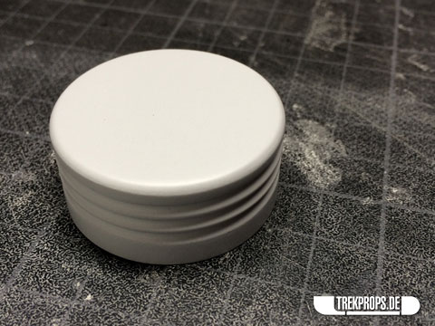
I noticed however, that the whole element was not tall enough and did not match the original prototype. I simply sanded off too much of the bottom of the casting to make the surface smooth.
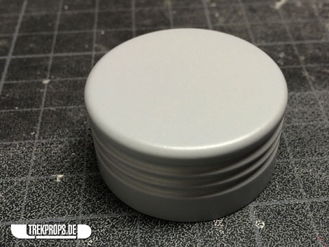
So I used styrene to extend the element like this:
A few layers of putty and primer later, with a little sanding in between, the new “end cap” was finished and ready to be molded.
And here are all of the Neutrino Probe molds with their respective prototypes. Seven pieces in total, which is quite a lot, now that I’m looking at all of them together.
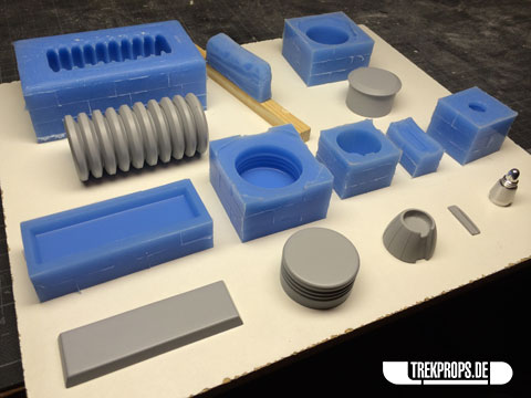
In the next blog post I will cover the casting process for these parts and the unique problems I had to solve to make that happen.
As always, if you want to follow my work more closely, you can follow me on Twitter (@trekprops) to get more frequent updates on what is happening in my workshop.
If you have any questions or observations, you can of course also E-Mail me or leave a comment below. I’m looking forward to hearing your thoughts! 🙂

2 Responses to “Work in Progress: Neutrino Probe – Molding”
Work in Progress: Neutrino Probe – Casting on: May 30th, 2014 at 01:36
[…] problems that presented themselves while casting the Neutrino Probe components for which I have all the molds now. Also, I tried a few new techniques with these parts to improve the appearance of the product […]
Anonymous on: May 30th, 2014 at 13:52
[…] to you are some of the problems that presented themselves while casting these components from my molds. Also, I tried a few new techniques with these parts to improve the appearance of the product and […]
Post a Comment
Want to see your picture next to your comment? Go get a Gravatar!